Half And Full Wave Rectifier Circuit Diagram
Half wave rectifier basics, circuit, working applications, 50% off Rectifier wave half full circuit diode voltage diagram output waveform ac figure input positive cycle dc principle working converts Rectifier circuit diagram
half wave full wave and bridge rectifier diagram - IOT Wiring Diagram
Rectifier transformer tapped output input waveform Single phase half wave rectifier- circuit diagram,theory & applications [diagram] circuit diagram rectifier
Half wave rectifier circuit diagram pdf
Half wave rectifier basics circuit working amp applicationsRectifier voltage circuits circuitdigest debashis Rectifier circuit diagramHalf and full wave rectifier working principle.
Half wave full wave and bridge rectifier diagramHalf wave and full wave precision rectifier circuit using op-amp Half wave rectifier circuit simulation download scientific diagramHalf wave rectifier(explanation).

With neat circuit diagram and waveforms explain the operation of full
Rectifier waveformFull wave rectification diagram Half wave full wave and bridge rectifier diagramHalf wave rectifier.
Rectifier diode circuitdigest breadboard diodesDescribe the half wave rectifier using diode Full wave rectifier circuit working and theoryRectifier wave half.

Half wave rectifier circuit
Half wave and full wave precision rectifier circuit using op-amp .
.

![[DIAGRAM] Circuit Diagram Rectifier - MYDIAGRAM.ONLINE](https://i2.wp.com/circuitglobe.com/wp-content/uploads/2015/12/HALF-WAVE-AND-FULL-WAVE-RECTIFIER-FIG-1-compressor.jpg)
[DIAGRAM] Circuit Diagram Rectifier - MYDIAGRAM.ONLINE

half wave full wave and bridge rectifier diagram - Wiring Diagram and

half wave full wave and bridge rectifier diagram - IOT Wiring Diagram

Half Wave Rectifier

Half Wave Rectifier Circuit

Half Wave Rectifier(Explanation) - YouTube

Half Wave Rectifier Circuit Diagram Pdf
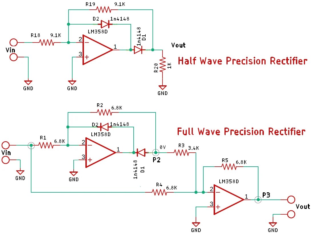
Half Wave and Full Wave Precision Rectifier Circuit using Op-Amp

Half Wave and Full Wave Precision Rectifier Circuit using Op-Amp